
Single transistor radio
Here is the circuit diagram of a simple radio that uses one transistor and few other passive components.The C6 and L1 forms a tank circuit which picks up the signal from your desired radio station.Diode D1, capacitor C2 and resistor R1 does the detection of the picked signal.The detected signal is coupled to the base of Q1 through capacitor C3.The Q1 gives required amplification to the signal.The resistor R2 is used to bias Q1.R3 limits the collector current of Q1.The audio output will be available at the collector of Q1 and it can be heard by using a high impedance head phone.This radio will work only at places where there is reasonable radio signal strength.
Circuit diagram with Parts list.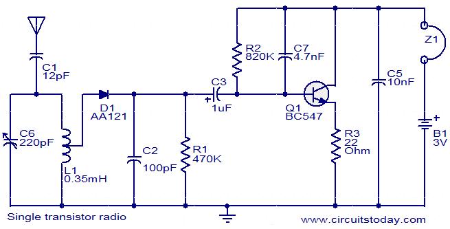
Notes.
- Assemble the circuit on a general purpose PCB.
- The circuit can be powered from a 3V battery.
- The antenna can be a 1 M long wire.
- The headphone must be a high impedance(2 to 3K) type.
- If diode AA121 is not available you can use AA112, AA116 or 1N34.
- The inductor L1 must be a 0.35mH, center tapped one.
- The radio can be tuned by adjusting the variable capacitor C6.
Read more: http://www.circuitstoday.com/single-transistor-radio#ixzz1HiHMYPWX
Under Creative Commons License: Attribution
Tidak ada komentar:
Posting Komentar